Convincing key figures
Compare conventional technology with cycle-controlled lathes from SEIGER
Convincing key figures
Compare conventional technology with cycle-controlled lathes from SEIGER
A comparison of practical applications
The easiest way to convince yourself of the cost-efficiency of our cycle-controlled lathes is to compare them with conventional technology. Using a few real practical examples, we will show you how you can save up to 60% of your time. Explore the time line for each process in our clear diagrams below.
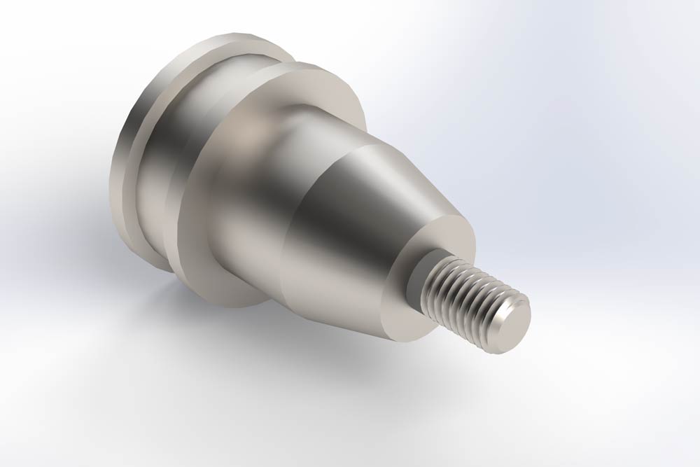
Production of simple parts in small series
Contrary to expectations, the set-up time for SEIGER cycle-controlled lathes is significantly shorter. While the conventional lathe is still being set up, the component on a SEIGER lathe has almost been finished. The servo-controlled axes in particular permit significantly higher machining speeds.
To display the absolute time in minutes, please move your mouse pointer onto the fields.
Working steps conventional lathe
Working steps Seiger cycle-controlled lathe
- Prepare the machine
- Set up the tool
- Clamp the workpiece
- Create the program
- Measure the workpiece
- Rough down the workpiece
- Finish the workpiece
Production of complex individual parts
The advantages of cycle-controlled lathes from SEIGER become particularly obvious where complex components are involved. Beyond the outstanding values for machine set up, our cycle-controlled lathe remains as flexible as a conventional lathe yet reproduces results as reliably as a CNC lathe.
To display the absolute time in minutes, please move your mouse pointer onto the fields.
Working steps CNC lathe
Working steps Seiger cycle-controlled lathe
- Prepare the machine
- Set up the tool
- Clamp the workpiece
- Create the program
- Measure the workpiece
- Rough down the workpiece
- Finish the workpiece
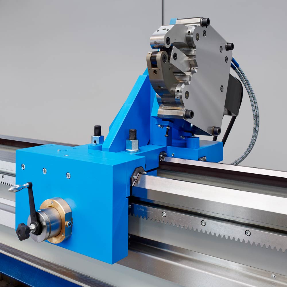
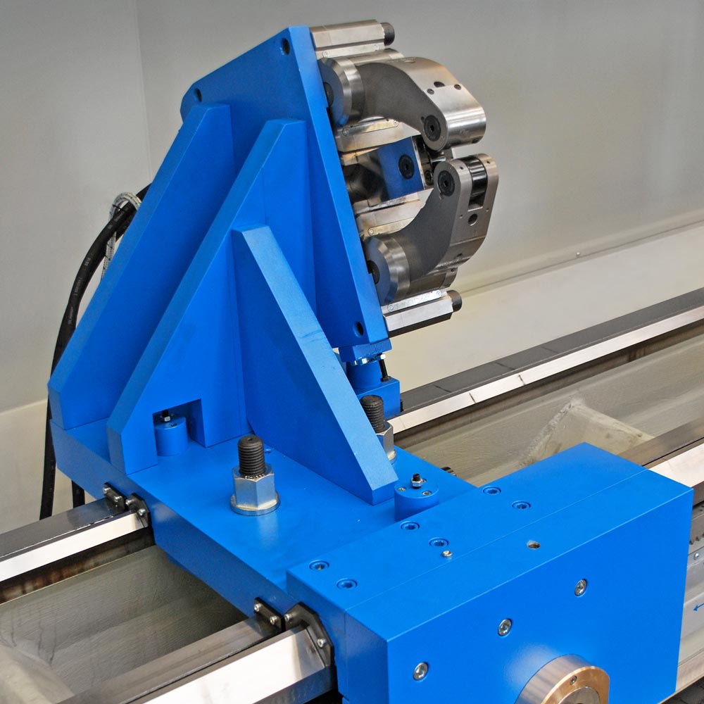
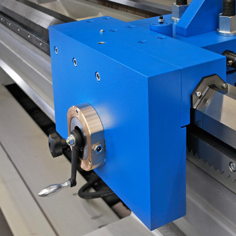
Positioning of a rest on lathes with large center distances
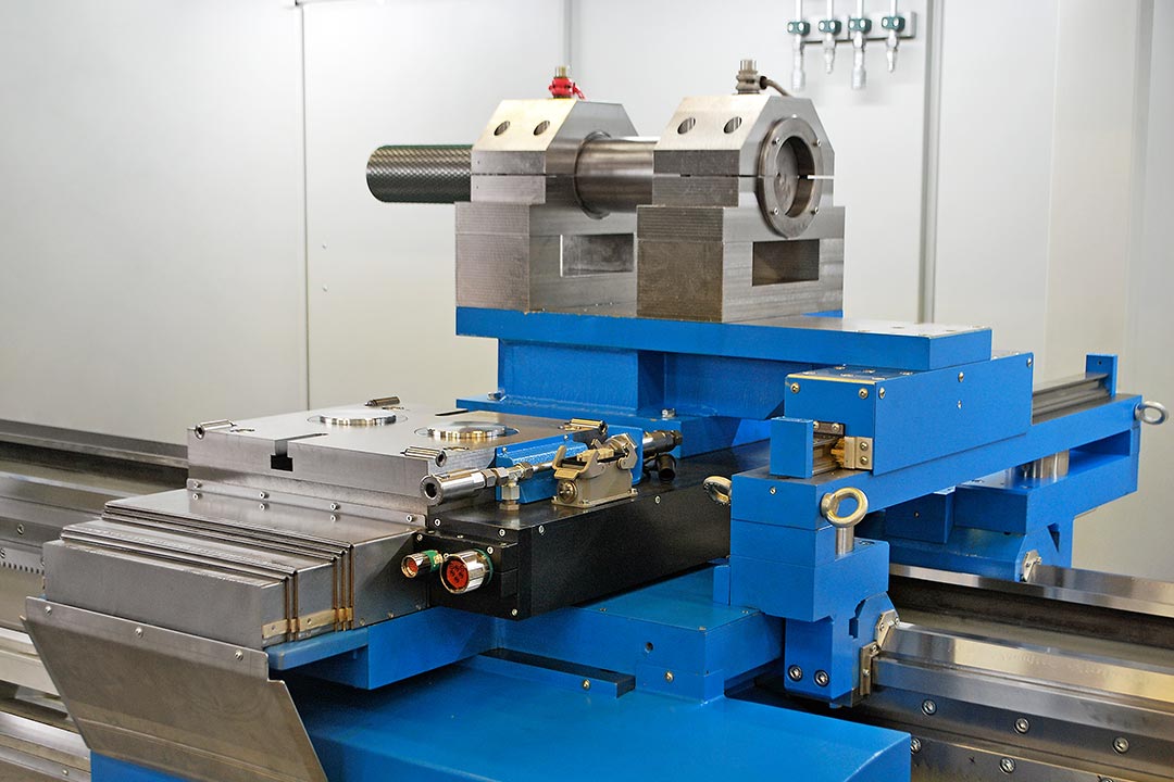
Where long parts are manufactured, the use of rests is obligatory. The planning of the work sequence is decisive in this case, so that no unnecessary rest change-overs occur. SEIGER rest adjustment makes fast and flexible displacement of the rest on the entire machine bed possible. At the same time, fast removal of the rest assembly from the machine bed takes place thanks to the intelligent coupling and decoupling solution for the drive assembly.
To display the absolute time in minutes, please move your mouse pointer onto the fields.
Working steps without SEIGER special adjustment system
Working steps with SEIGER special adjustment system
- Prepare crane
- Attach rest
- Loosen screws
- Remove clamping plate
- Position rest
- Mount clamping plate and tighten screws
- Release crane
- C. Loosen screws
- H. Latch adjustment into place
- E. Position rest
- I. Tighten screws
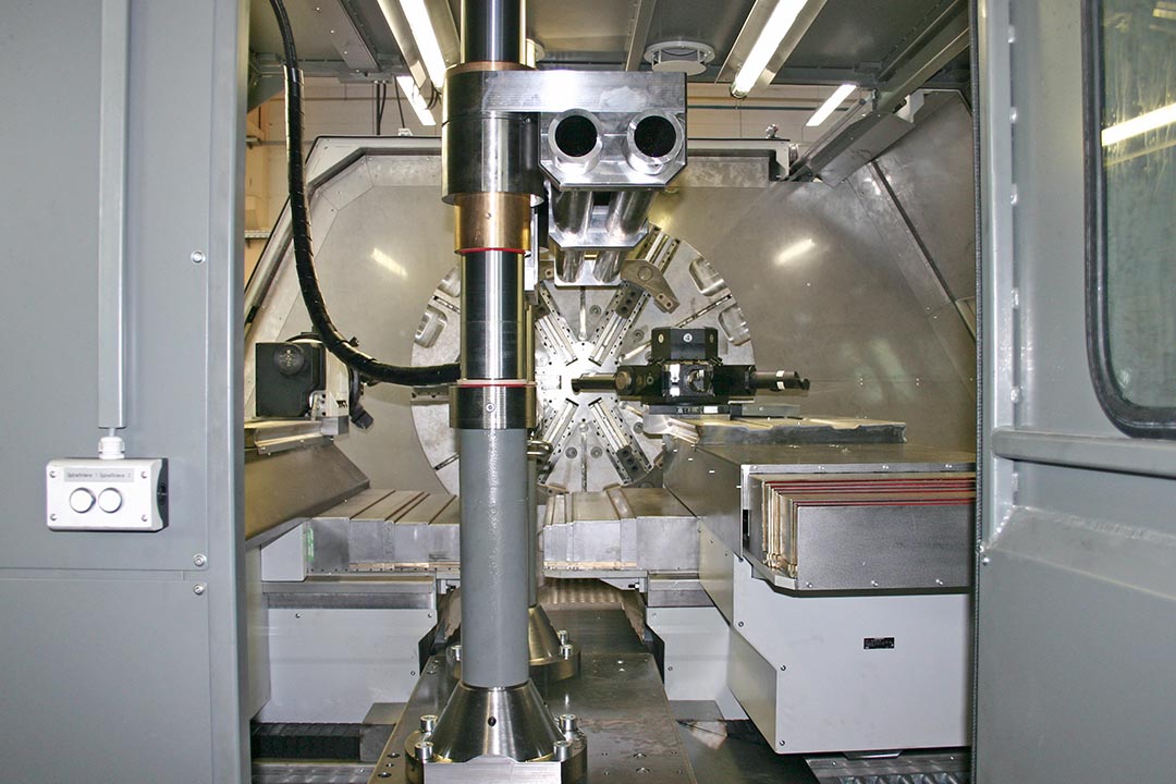
Setting up a turret / drilling-milling unit / boring bar clamping support
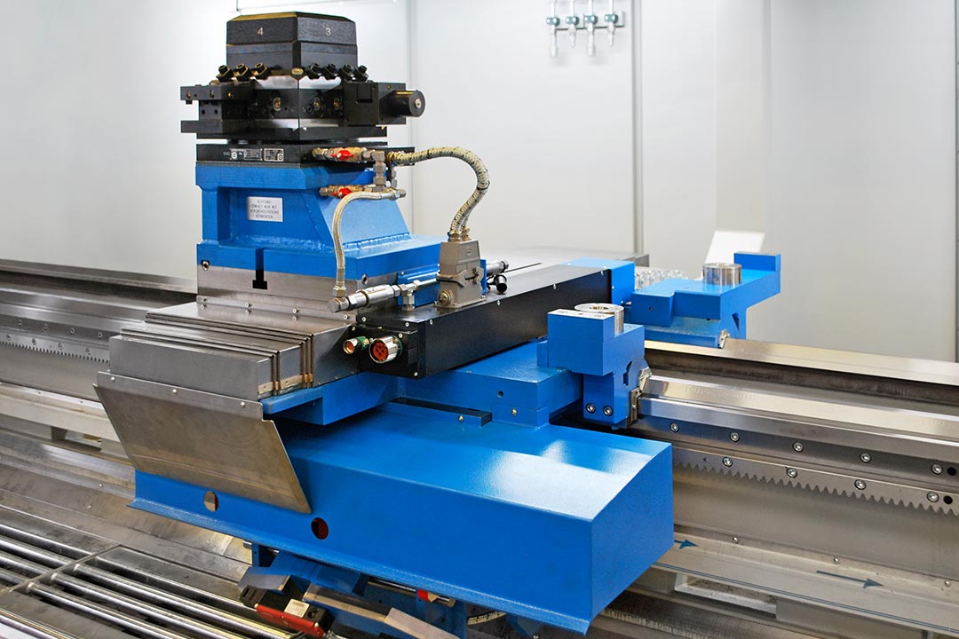
Highly dynamic tool changeovers or even the complete changing of entire tool systems comes to bear particularly when very complex components are manufactured. We do justice to this requirement with the SEIGER quick-clamping system. This method makes it possible to change between automatic tool change systems (e.g. turrets to driven milling/drilling units through to boring bar clamping supports).
To display the absolute time in minutes, please move your mouse pointer onto the fields.
Working steps without SEIGER quick-clamping system
Working steps with SEIGER quick-clamping system
- Prepare crane
- Press buttons
- Loosen screws
- Remove assembly
- Set new assembly in place
- Align assembly using dial gage
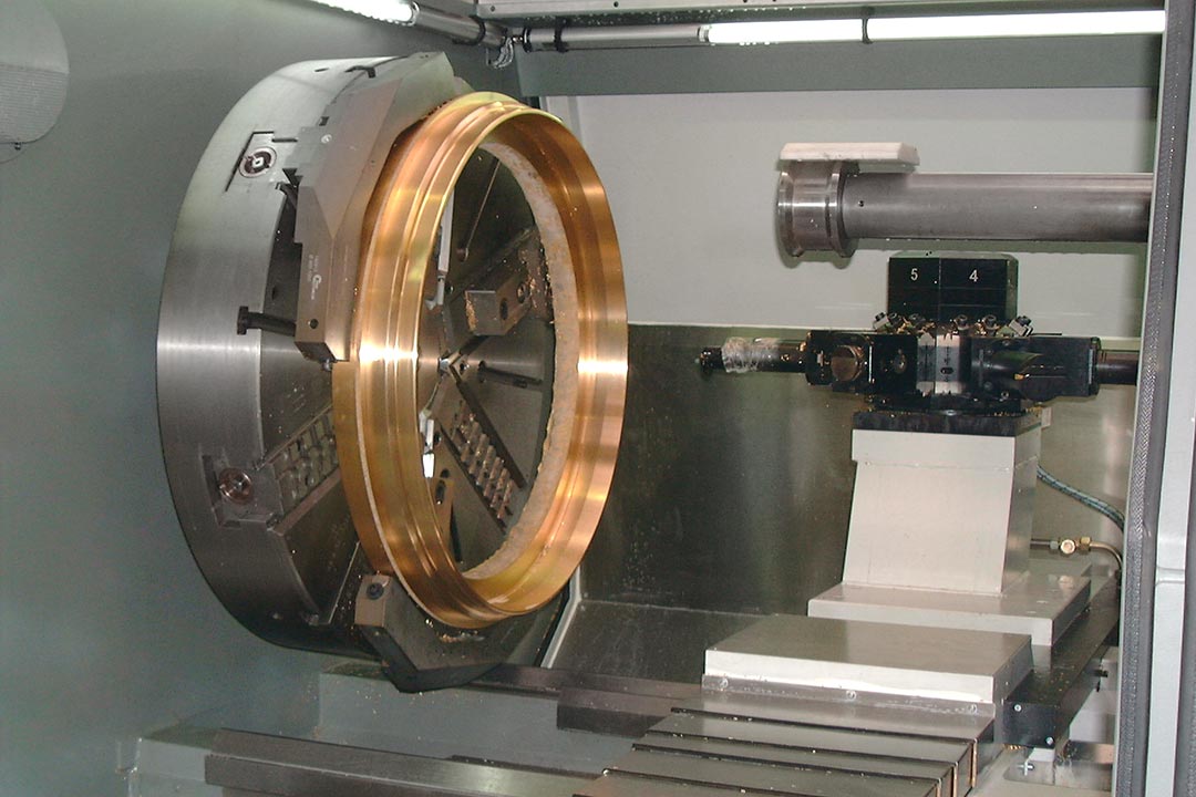
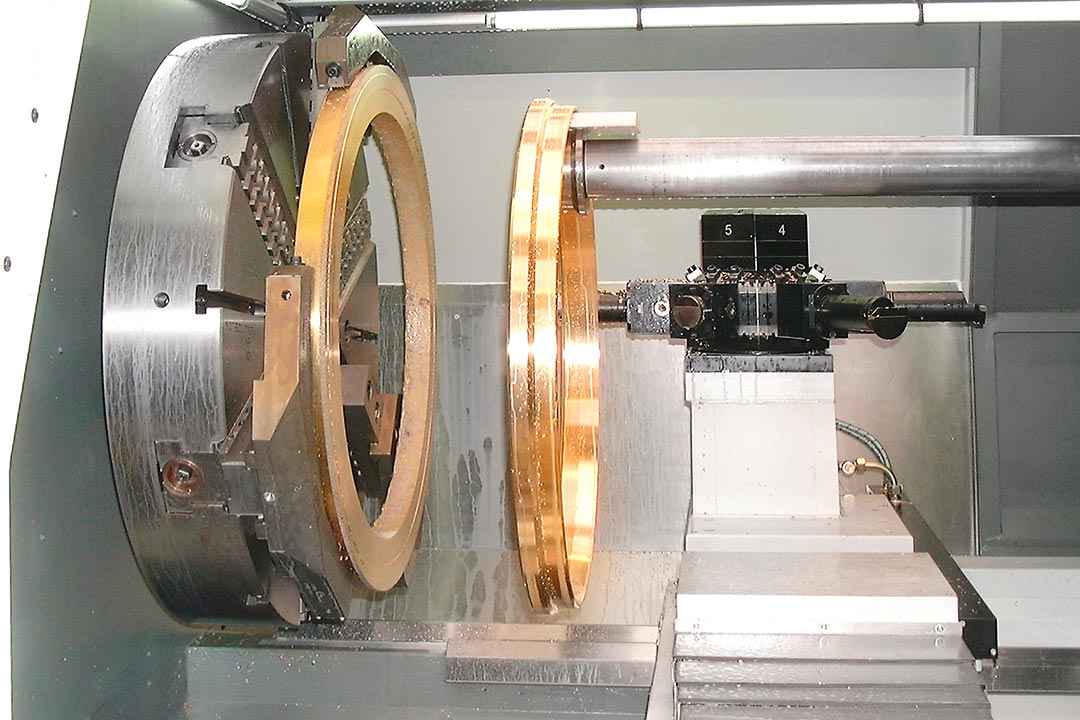
Slicing a ring-shaped component with a large diameter
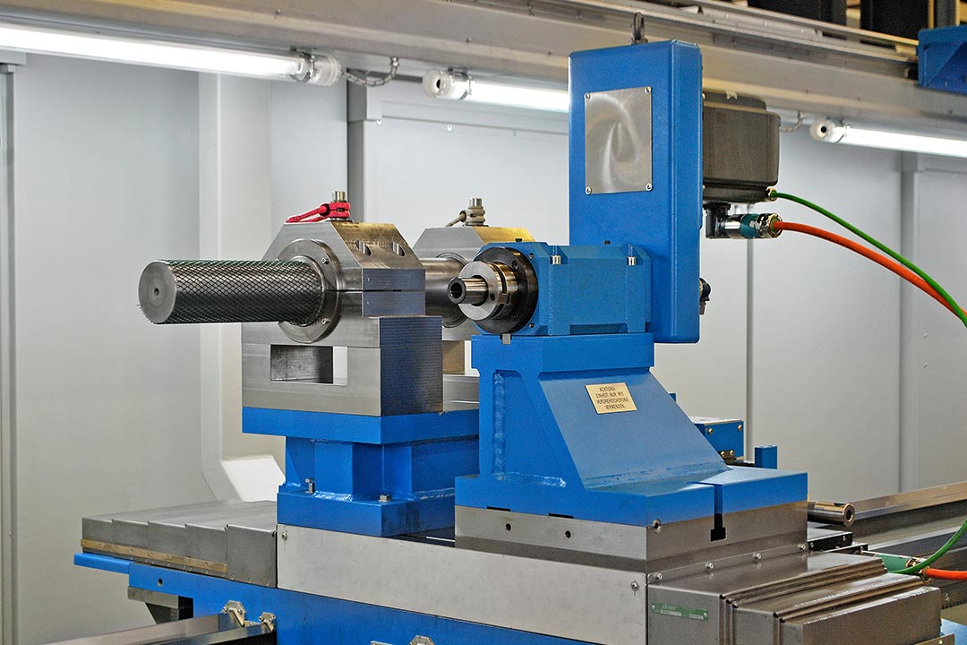
In the field of large turned parts with a short length, particularly in the field of facing lathes (face lathes), SEIGER has a special convincing innovation to offer. When manufacturing workpieces with large diameters and small component depths, certain handling problems usually occur which the SEIGER parts gripper compensates as a controlled axis. The diagram clearly illustrates the striking time saving.
To display the absolute time in minutes, please move your mouse pointer onto the fields.
Working steps without SEIGER parts gripper
Working steps with SEIGER parts gripper
- Program workflow: turn the inner and outer contour
- Slice component
- Interrupt the program
- Loosen the finished part by hand using auxiliary tool + lifting gear
- Set down component
- Program workflow in automatic mode: turn the inner and outer contour
- Program workflow in automatic mode: slice with parts gripper
- After end of program: set down component